When looking at the view geometry numbers reported by my Pimax 5k+ I noticed something strange, so I decided to visualize the native and the parallel projections and since the pictures turned out to be better than words, I decided to share them here.
But first I need to explain, what is actually on them, so people do not get confused or misread them:
The geometry
is taken from the following values reported by the headset to OpenVR:
- Eye to head transform matrix for each eye, which gives the orientation and the location of the “eyes” in the “head” space.
- The projection “raw” values, which define the viewing frustum for each eye.
The shapes
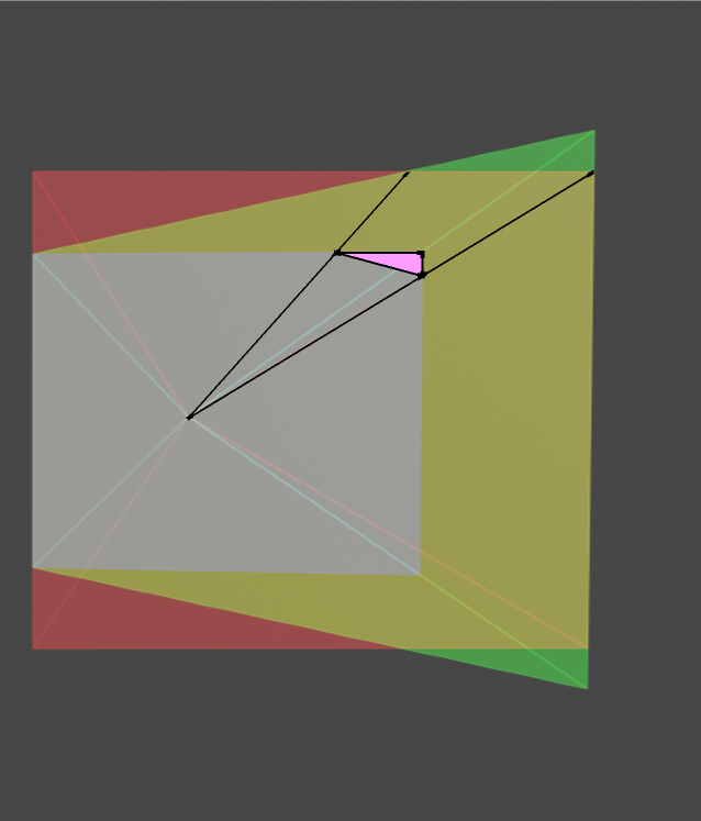
are the visualization of the viewing frustums which the application gets from the OpenVR. The wireframe is just helping imagine the the shape of the frustum and its center = eye point. The rectangles are the representation of the area (in arbitrary unit) into which the application renders the image (i.e. a canvas). They respect the aspect ratio of the recommended render target resolution but they do not represent the panels as the panels and recommended render target res are two completely different things.
These “projection planes” seems also awfully close to the eyes, which would not be possible, if they were panels (the drawing is in scale in a sense that the distance between the eyes corresponds to my IPD ~ 70 mm).
The reason why the distances from the eyes to the projection planes do not correspond to the distances from the eyes to the panels on the real headset are the lenses, which magnify the panels (=bring them virtually closer).
On the other hand, even though the visualizations do not represent the actual hardware design, they are perfectly in scale with the geometry the application uses when it renders the scene, which means all the angles and orientations are accurate.
The projection planes and their colors
There are three different viewing frustums merged into one image:
Native projection planes represented by the “white”-ish rectangle (the smallest one), represent the “native” mode of Pimax. The planes are canted outwards by 10°.
Native planes projected onto the parallel plane are green. These represent the shapes which the headset should render if it wanted to cover the original native view by using the parallel projection. I.e. projection onto the plane parallel to the face.
Pimax parallel projection views are red.
Since the colors mix, where green and red overlaps you see yellow. The white-ish plane is originally blue (as visible on some “top” views), but gets its final color from the combination with red and green. The different coloring also offers an insight about how Pimax handles the parallel projection.
If it would be possible, the headset would need to render only into the green area (when running in parallel projection mode), but since the normal rendering pipeline does not usually supports rendering into non rectangular frustum, the Pimax had to choose a trade-off.
Where you see the red triangles, these are the areas which are rendered, but never used, as they are outside of the view the canted panels can display. On the other hand, the green triangles are the areas which ideally should be rendered, but are probably safe to discard, because the corresponding area on the panel is not visible anyway (for other reasons, as for example lens distortion, or dimensions).
Pimax decided to use the same “pixel density” in all modes, so the surfaces (represented by different colors) are directly related to the number of pixels in those areas. In other words, by comparing the surfaces, we can estimate the difference in performance requirements for particular modes.
Because the “front view” is not really giving out the 3D nature of the visualization, I decided to add also the “top view”, which should give some additional clues about what is actually on the picture.
There is one thing which Pimax can improve for parallel projection though. The red areas can be masked by hidden area mask so the application will not render there (though geometry would still need to be processed). I wonder why they have not done it since the driver already supplies the mask, which seems to be just a static mesh, hardcoded for the particular mode.
Small FOV
Recommended render target size (SteamVR SS=100%, PiTool RQ=1.0):
    PP off: [2636, 2632]
    PP on:  [2784, 3288]


Normal FOV
Recommended render target size (SteamVR SS=100%, PiTool RQ=1.0):
    PP off: [3200, 2632]
    PP on:  [3852, 3288]


Large FOV
Recommended render target size (SteamVR SS=100%, PiTool RQ=1.0):
    PP off: [4268, 2632]
    PP on:  [6948, 3288]


(edited by Neal, to fix a confusing misspelling)